Low Power Devices are becoming an increasingly important area of embedded electronics design. From wearables devices to handheld equipment to remote applications, a large number of devices have batteries as the primary source of power supply. So comes the consideration of designing smart and power efficient devices.
It requires a very unique design approach that balances the functionality, performance and energy consumption.
Below are some practical techniques that help optimize embedded systems for maximum possible energy efficiency.
Power management is the most important aspect in designing Ultra Low Power (ULP) systems.
It must be taken into account the amount of effective energy vs the energy lost in by-operations. Both hardware and software should be optimized for this. Batteries should be selected wisely considering the amount of current consumption per hour compared to the acceptable amount of hours per battery.
Hardware Optimization is a crucial stage in optimizing system power consumption. There are several ways to accomplish this and it varies with the type of hardware and application. Some common hardware optimization technique are given below:
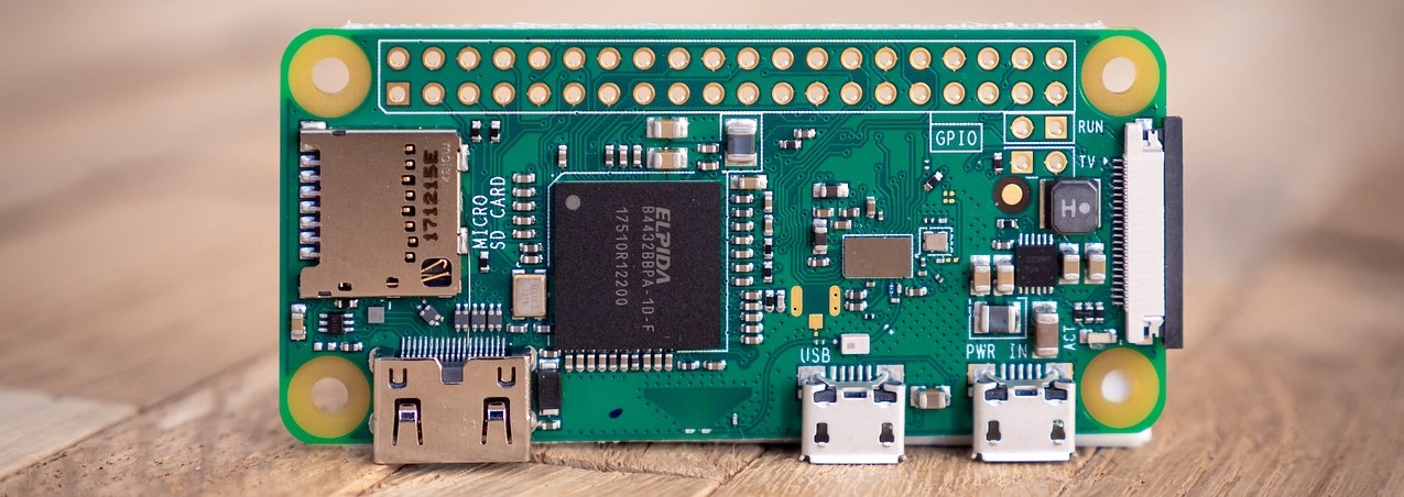
Nowadays, a lot of embedded electronics use Microcontrollers (or MCUs). Their power consumption depends on several factors including their Processing Power and Clock frequencies.
Many of them feature Sleep modes in lighter loads which disables some power hungry stages of the MCU. Wake-up is usually supported by interrupt pins which makes it very convenient to pair with sensing applications where sensors act as an Interrupt Source.
Some common examples of such MCUs are:
Linear Dropout Regulators or LDOs are very commonly used to obtain regulated voltages. Often stepping down the voltage to a desirable level. As the difference between Vin and Vout Grows bigger, the power losses across them linearly increase.
The best alternative to using LDOs is Switching Regulators. Their principle of operation is to adjust the Output Duty cycle to obtain the desired or preset output. They have no significant losses across them except a very small amount of current being used by the switching controller and some negligible leakages.
Such devices could be more expensive compared to LDOs. They require more components around them to work and take a larger area but nowadays, industry has developed better switching regulators tailored to specific applications significantly optimizing the area and need for less components.
The alternative to both techniques could be sometimes as simple as using a series of diodes to obtain the desired voltage but that bears some drawbacks like the noise and fluctuation in input is directly transparent to the output and also output voltage is not fixed and varies directly with the change in input. Though in some specific applications, this technique is very useful.
Digital Electronics often require Pull-Up Resistors for adjusting logic Levels. Typical applications include Pull-Up resistors for I2C Bus or setting the configuration of Semiconductor devices to select the modes of operation.
Pull-Up resistors can contribute to a significant draw of current which is usually consistent and unavoidable. The best way to reduce power consumption across Pull-Up Resistors is to use higher values of resistors.
For Example: a 10k Pull-Up Resistor with 5V has a current draw of approx. 0.5mA. Replacing it with a 220k Resistor will maintain the same voltage with current draw of 0.02mA which is 25x less.
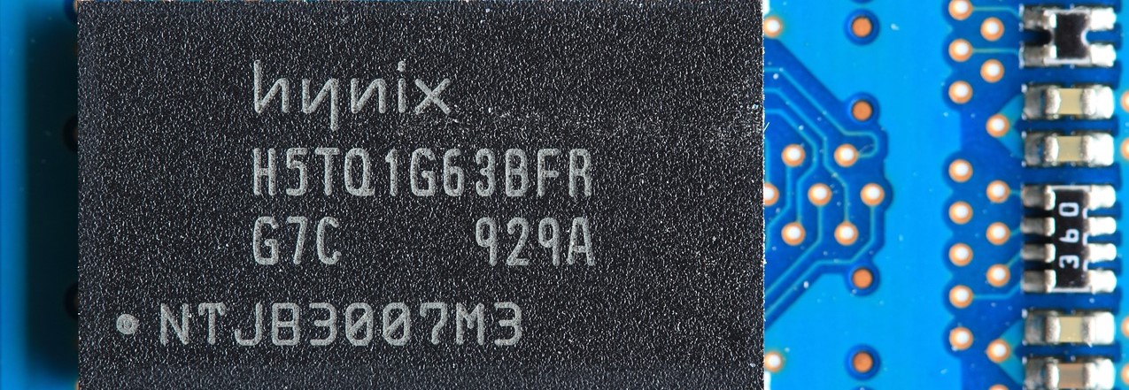
NOTE: Bigger resistance makes for a weaker pull-up effect. The bus speed must be taken into consideration when deciding for the resistance. For Example, a 10k Pull-Up on a DDR3 Bus operating at 1600MHz will induce a significant amount of delay and the Memory Bus is likely to misbehave. It requires a balance between performance and power consumption.
In analog circuits, voltage dividers are often used to set the operation modes of OP-AMPs or maybe setting the reference voltage for a circuit.
Voltage dividers do come with a significant amount of current loss which can be calculated for both resistors using Ohm's law and adding it up.
The catch here though is to use a higher multiple of resistance.
For Example: Using 2x 1k resistors in series as a voltage divider with source of 5V results in 2.5V output.
The current loss here is 5mA.
Replacing the circuit with 2x 200k resistors results in 0.06mA.
This technique is very helpful in optimizing the voltage dividers that are being used to obtain reference voltages.
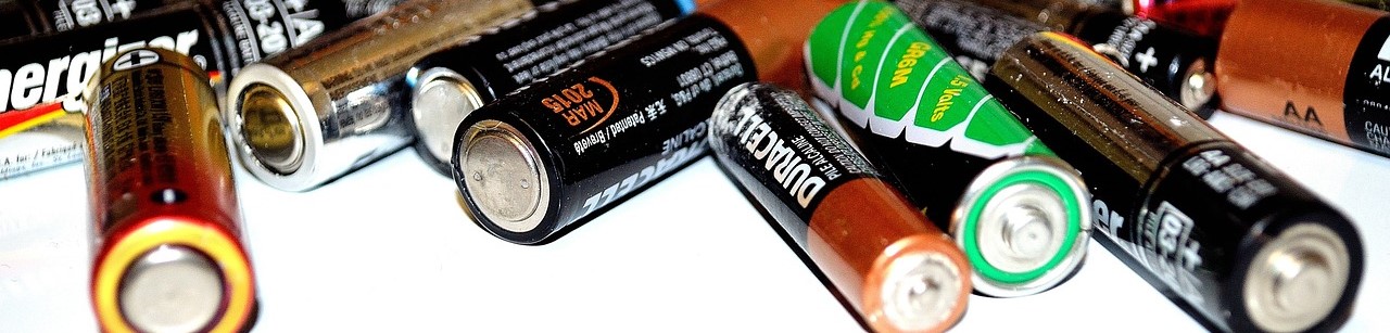
The selection of batteries is sometimes very confusing and it requires a balance between battery life, size and cost. The rechargeable batteries are an attractive option for applications like handheld devices but they bear a significant amount of self discharge which makes them unsuitable for long term operations. They are commonly used in applications where recharging after a certain period of time is possible.
If an application is intended to work for several months or years, rechargeable batteries are not a sensible choice. The non-rechargeable batteries have a lesser amount of self-discharge so they are generally more appealing for very long term operation.
The critical point to consider here is that all the batteries have a certain amount of current discharge limits. It must be taken into consideration that the peak current draw is within the range of continuous discharge specifications of the battery.
Understanding the application requirements and utilizing the system resources, embedded systems have a lot of potential of optimization in software. The deeper we have the system understanding, the better it could be optimized. To reduce power losses, it’s better to reduce the number of Hardware Abstraction Layers (HAL) as much as possible. Abstraction layers are typically created to make the software development easier but they’re more generic instead of purpose built so carry a lot of extra payload that isn’t necessary anyway.
Sleep modes for microprocessors and Microcontrollers are a key to power optimization. They should be utilized whenever possible with a wakeup plan on load. Aside from that, microprocessors sometimes provide the flexibility to reduce clock speeds when loads are minimal. If more than one cores are available, it’s helpful to disable the performance cores under light loads while efficiency cores keep running to handle lighter threads.
For Example: ESP32 has two performance cores and an Ultra Low Power Processor. If the Application is running on One core, the second should be disabled. Even further, if application takes a long time to monitor certain logic levels, it’s better to keep both cores OFF and run the GPIO monitoring processes on the ULP Processor only.
Data Structures are highly responsible for larger power consumption during the execution time. If data structure requires a lot of traversing, it consumes unnecessary clock cycles and hence more time resulting in more power loss. More efficient data structures should be utilized considering the type of application for an optimized power efficiency.
For Example: In situation where a lot of tighter loops are required, a sequentially traversed data structure may prove more efficient compared to random access data structures based on the computation required behind the scenes to compute their physical addresses.
In the case of sensing environments, it might not be necessary to keep monitoring data all the time. In such scenarios, it’s better to monitor sensors after certain intervals of time while keeping the system in sleep (or at least semi-sleep) rest of the time.
For Example: In environmental temperature monitoring, it is not necessary to keep reading data from sensors several times per second. If sampling time is set to, let’s say 1 sample per minute while keeping the sensor off the rest of the time, that can save a reasonable amount of power.
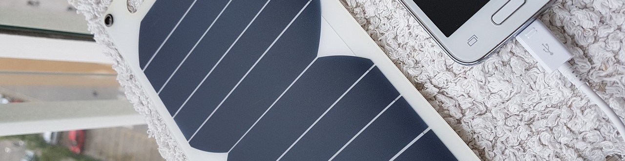
Energy harvesting techniques are very helpful to improve the Up-Time of the system. Energy harvesting sources such as Solar, Kinetic or Thermal could be used as a secondary source of supply as well as to recharge the batteries for later time.
For Example: The Soil Monitoring nodes often deployed in large crop field can be equipped with Solar Cells to run on the Solar Energy and save batteries during the day or even better to recharge the batteries for a longer runtime.
Most of these techniques are personally practiced by me during my hardware design journey and it helped me achieve more than desired results. I highly recommend them but it’s important to consider that there are often trade-offs between cost, performance, power efficiency, size etc. Every Embedded Engineer should properly understand the system requirements to implement any of these practices.